
Early Interceptor Engine-Bay
The quest for originality during a restoration can be demanding, particularly when correct ‘factory’ detail is important. One feature of a Jensen which takes time and expertise to get just right, is the engine-bay.
Many decades have elapsed since the cars were first built, and in that time, all manner of detail may have been changed. The Museum looks at the detail of an Early Interceptor engine-bay. These cars, with all but two using the Austin 6 cylinder engine, were produced by Jensen Motors between 1950 and 1958.
We should note, the car was simply named ‘Interceptor’, when it came out in 1950. A name put forward by Jensen enthusiast, and friend of the Jensen brothers, Lord Strathcarron.
When the Italian-designed car took over the name ‘Interceptor’ in 1966 , many in the factory, started to call the 1950s cars as Early Interceptor, as a way of differentiating between the two. That designation has stuck with the car ever since.
In regard to Early Interceptor engine-bays, undoubtedly there is more to learn about subtle changes that may have taken place, and at what chassis numbers these changes happened. However, this feature should provide a good starting point to those interested in these rare cars.
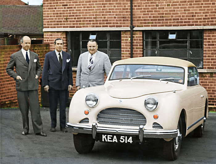
Early Interceptor chassis number ’52’. One of just six Early Interceptors made in LHD form. The photograph was taken in 1954 at the Carters Green factory. The Jensen brothers photographed together with the new owner of the car, Eigel Jensen from the USA.
Early Interceptor Engine-Bay | An Overview
Apart from just two cars, which were fitted with V8 engines, the Early Interceptor was fitted with the Austin 6 cylinder engine as its power plant (all DS 5, apart from the last car which had a DS 7).
The way the body was designed, meant it was a tightly packed engine-bay, and for some jobs, such as changing, or re-coring, the radiator, it means the entire front body of the car has to be removed.
Many of the images showing various engine-bay details are of the Museum’s Early Interceptor, chassis ’63’. This car had last been on the road back in the 1970s, and the car remained unmolested , and particularly original in all respects.
This was also the case with the engine-bay, which apart from routine service work, everything was as it had been when it left the factory in 1955. This history makes ’63’ an excellent default car for understanding how the car would have looked when it left the factory.
Early Interceptor Engine-Bay | Engine-Bay Details | Austin DS 5 Engine
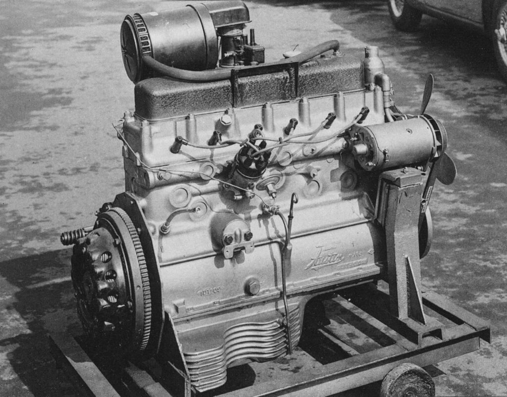
The Austin 6 cylinder engine. The units were delivered to Jensen Motors in their stock Austin colours. Jensen Motors would remove the ancillaries and spray the engines black. This was a practise that continued throughout production of Jensen cars.
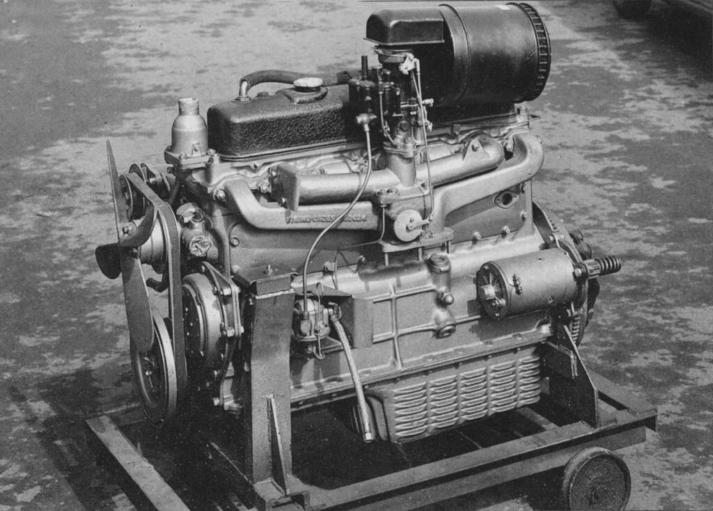
Nearside view of the Austin engine, showing the carburetter, inlet manifold and exhaust manifold. The starter motor positioned towards the lower rear of the engine.
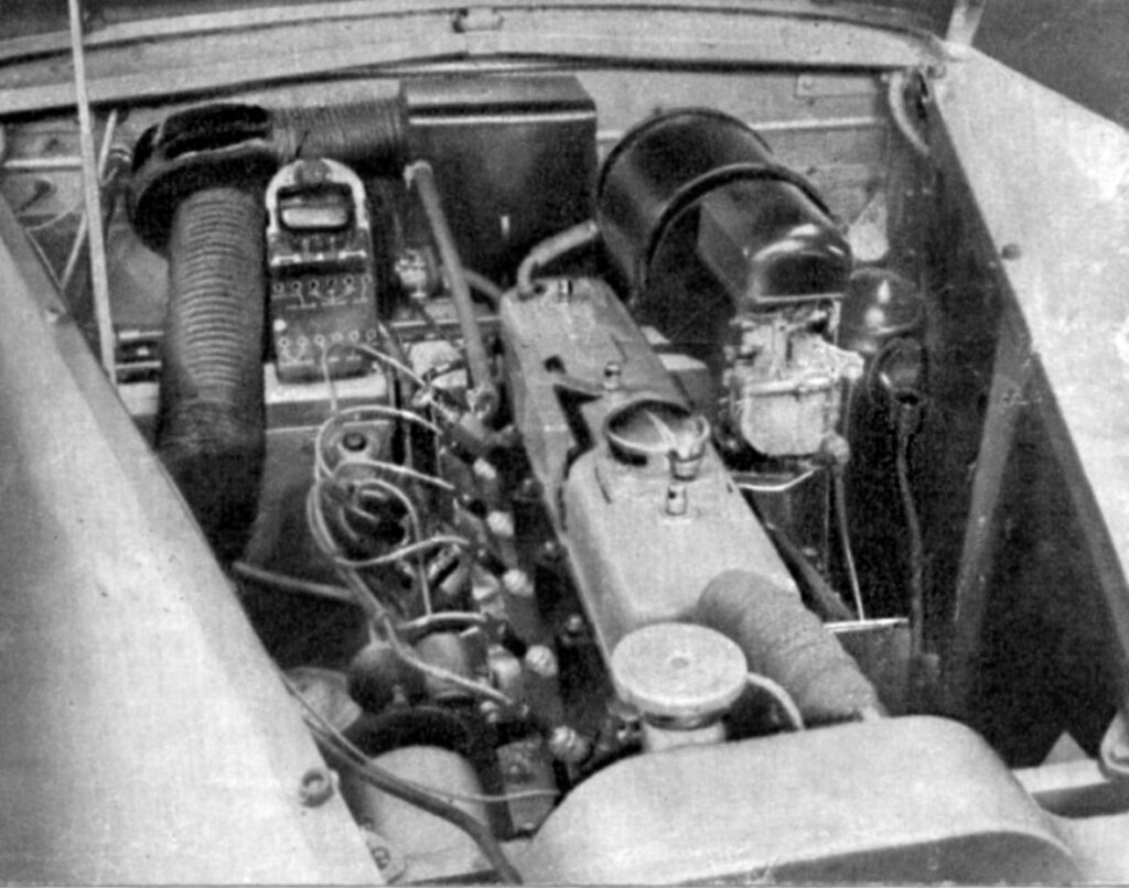
A period photograph showing the engine-bay of Early Interceptor chassis ‘5’. This particularly early car has various engine-bay details that were subsequently changed on later cars. Notably, the colour painted bulkheads, which were quickly changed to the traditional factory black. Additionally it should be noted that this car doesn’t use the Neolangite heat resisting panels to the lower bulkheads, which came into use during 1952. The inspection lamp socket is mounted just above the Voltage Regulator. A slightly different rocker cover is in use. The coil is mounted down by the Dynamo, rather than attached to the rocker cover. The radiator has the cap mounted on an additional section coming out of the side radiator, rather than being on the top. Of interest is a socket to the viewers right of the carburetter. See below.
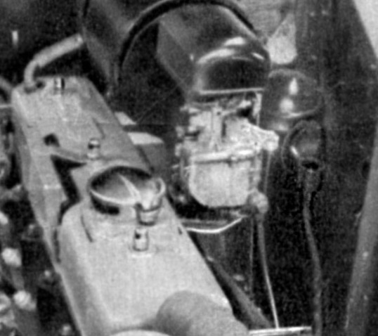
Detail of the chassis number ‘5’ engine-bay. The socket to the viewers right of the carburetter is a connection socket for the immersion heater. Built into the lower water connection between the radiator and the cylinder jacket, it could be coupled to the domestic electric supply in winter. A clever idea indeed, however, anti-freeze was slowly becoming more popular, which did away with the need for such a gadget. It was deleted off later cars, but at this stage, we do not know at which chassis number that occurred.

Period photograph of an Early Interceptor engine-bay (chassis number not known, but thought to be an earlier produced car with a typical Austin DS 5 engine). The engine unit in black paint finish (Jensen painted all engines black), and with a red painted rocker cover. The typical Lucas orange spark plug leads with Bakelite plug ends can also be seen. Being a period photograph of the Early Interceptor engine-bay is immensely important to us. It helps us to work out how to restore an engine-bay to factory finish. Although there were subtle changes over the period of Early Interceptor production, most will resemble this.

Detail showing the Voltage Regulator and covered fuse panel to this period engine-bay photograph. Just to the viewers right of the fuse panel cover, is a small circular accessory / inspection lamp socket. This allowed the inspection lamp from the tool kit to be plugged in for working within the engine-bay at night. It would seem that on later cars this socket was moved to the interior dashboard. The explanation could be simple. If an owner had broken down at night, trying to fumble around to connect the lamp to the engine-bay situated socket could have been awkward. An interior mounted socket would mean the owner could connect the lamp inside the car, and then take the lamp to the engine-bay. Of the cars viewed so far, including chassis ’46’, ’56’, and ’62’, all had the socket mounted by the fuse panel. The Museum’s car, chassis ’63’ has the socket mounted inside the car, as has chassis ’88’.

A view of the driver side bulkhead on car chassis ’12’ (the ex-Strathcarron car). Interestingly, this car has an inspection lamp socket mounted to an aluminium plate just below the main fuse board. There is a small circular cap, which one removes to expose the socket. If this was an idea which was trialed but discontinued on most other cars, isn’t known. However, we do know cars chassis, ’17’ and ’18’ also had the same set-up. Other points of interest are a separate reservoir for the brake fluid and clutch fluid, and a small black plastic two pin socket which could take another 12V accessory. As one would expect, this car had an RF95 Voltage Regulator. This photograph was taken before the car’s later restoration, and the layout was largely original and unchanged.

Detail from the period photograph of the Early Interceptor engine-bay. This image showing the nearside bulkhead with indicator relays, including the Lucas DB 10 relay box. The chassis plate is mounted high up on the bulkhead. The position of the chassis plate did move from the upper bulkhead to the lower part of the bulkhead.

Photograph showing the entire bulkheads and engine-bay area of Early Interceptor chassis ’84’ with everything removed. One can see the central oblong hole where the heater system fits, and the square hole to the viewer’s right where the metal speaker box would fit. To the corner is the circular hole where the air supply would go, which offers a cold air supply to the passenger footwell.
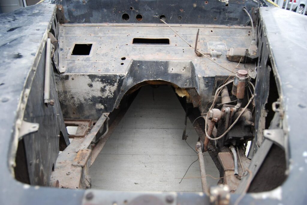
Photograph of the Early Interceptor chassis ’50’. This car was built as a LHD car, and with the engine removed shows the configuration for LHD very well. typically we can see the horizontal central hole for the heater unit, and the square hole to the viewer’s left-hand side showing the metal speaker box cover was in place, and hence, a radio system was ordered with this car. The Neolangite heat resisting panels are screwed into place on the lower bulkheads. Interestingly, a metal framed battery base can be seen at the base of the bulkhead to the viewer’s left. Generally the battery was fitted under the rear interior seat, if the battery was originally positioned within the engine-bay, or this was a later addition isn’t known.

Engine-bay of Early Interceptor chassis number ’63’. View from the offside. The main heater box can be seen in the centre by the bulkhead. A large black painted filter box sits on top of the Stromberg carburetter. Inside is a metal filter, which can be removed and cleaned. The cable attached to the offside inner panel runs from the bulkhead and then, incredibly, is routed through a purpose made circular hole in the radiator, to get to the bonnet release catch.
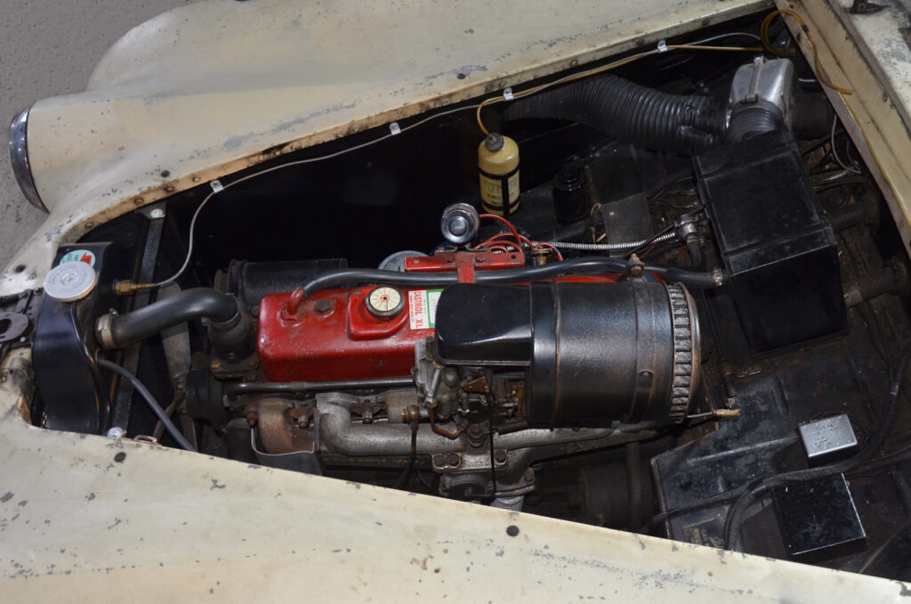
Engine-bay of Early Interceptor chassis number ’63’. View from the nearside. The metal temperature reading line runs from the radiator and then is attached to the offside inner panel, and then onto the bulkhead, and though to the dashboard temperature gauge. A Tudor windscreen washer bottle is also affixed to the driver-side inner panel, with a plastic tube running up to the bulkhead, and to the windscreen washers.
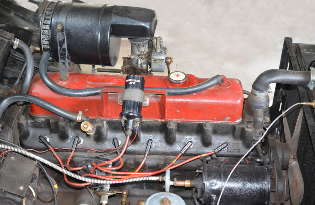
Engine-bay of Early Interceptor chassis number ’63’ with front body section removed. View from offside. The coil can be clearly seen mounted to the rocker cover. There was a specific clamp welded to the side of the rocker cover for the bolting of the coil and clamp. The Lucas coil was either in black, or sometimes silver. As far as we can determine, the aluminium engine fan was painted red. Some period red paint remains on the engine fan of ’63’.
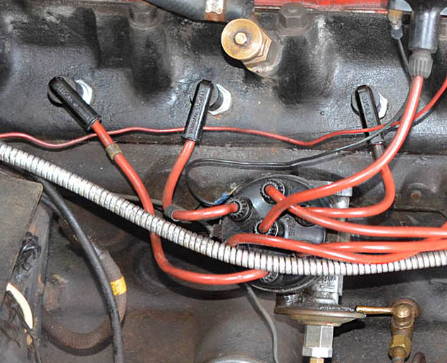
Close-up showing the standard equipment Lucas orange spark plug leads, along with the black Bakelite Lucas plug socket ends.
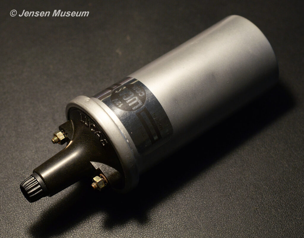
Lucas HA 12 coil. This silver example is dated 1966, but remained the same throughout the 1950s and 1960s.
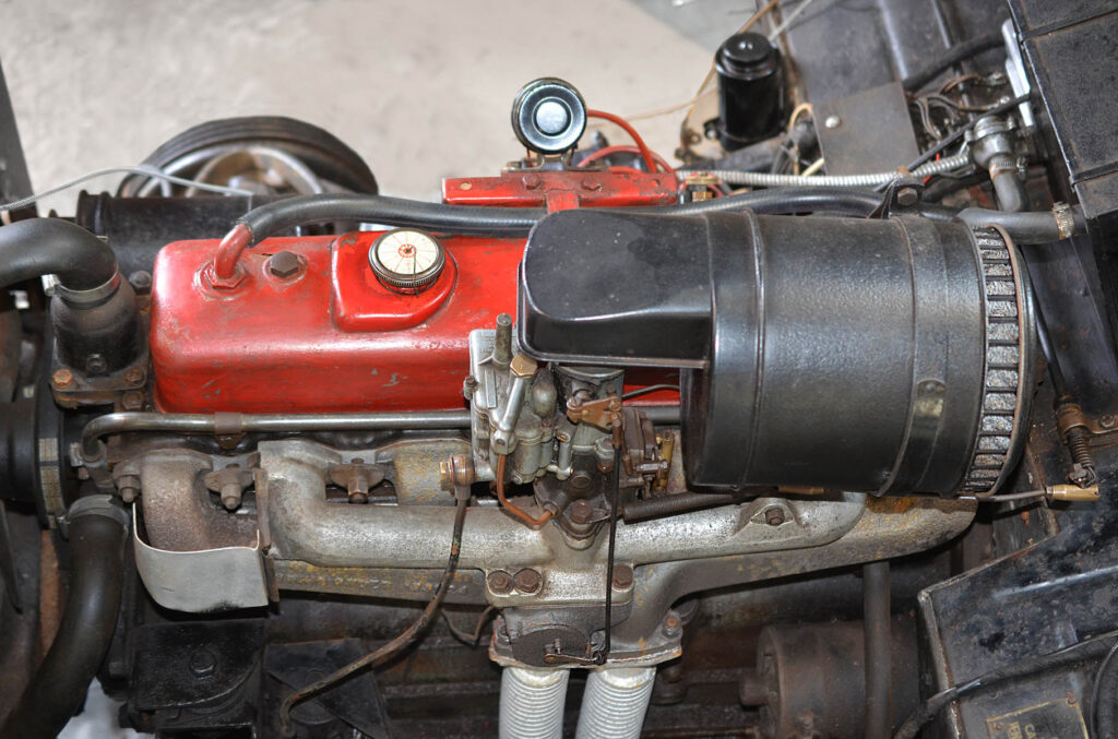
Engine-bay of Early Interceptor chassis number ’63’ with front body section removed. View from the nearside.
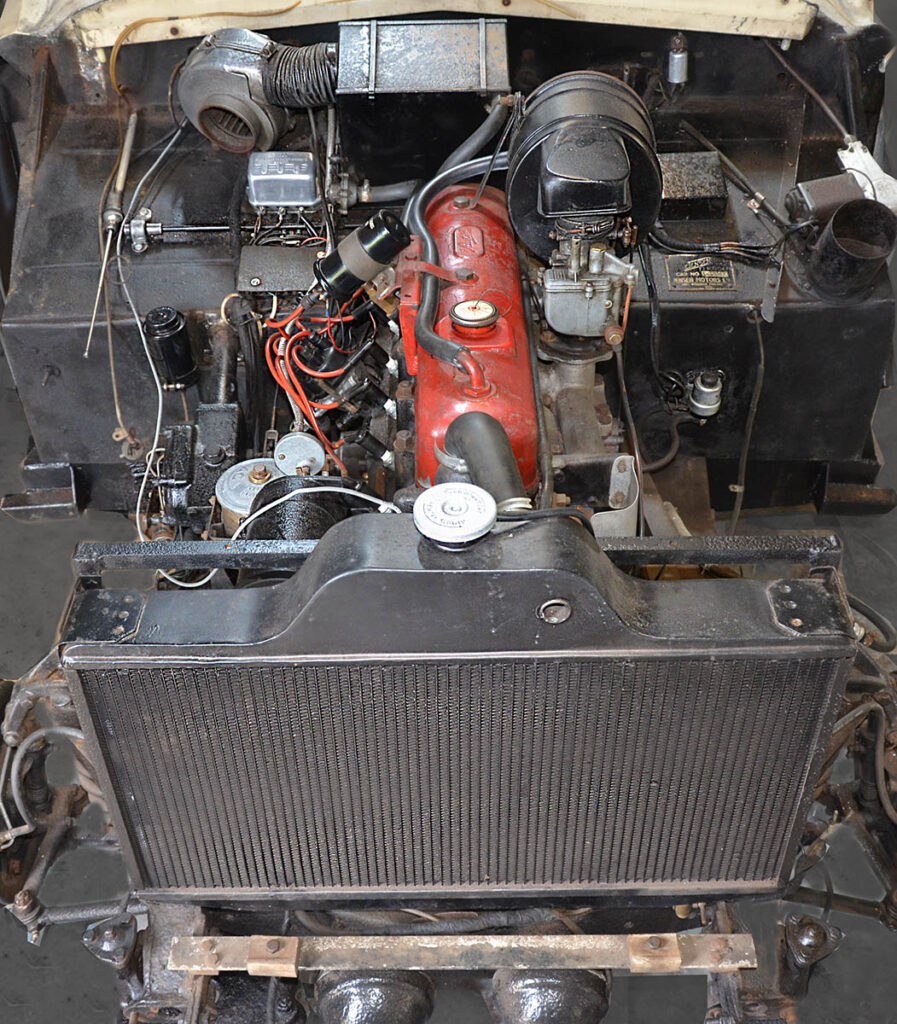
Engine-bay of Early Interceptor chassis number ’63’ with front body section removed. View from the front. This photograph shows the unusual shape of the Early Interceptor radiator, and the purpose made circular hole to the top nearside. The bonnet release cable runs through this hole to the catch. To the offside bulkhead can be seen the black painted metal brake fluid reservoir, and across to the nearside bulkhead can be seen the starter solenoid with starting button to the top of it. The Stromberg carburetter can also be clearly seen, along with the connection point of the metal filter housing. At the base of the radiator is an aluminium section with two wood fillets. The wood fillets are two of the fixing points for the front body section. The large Lucas horns can just be seen at the base of the image.
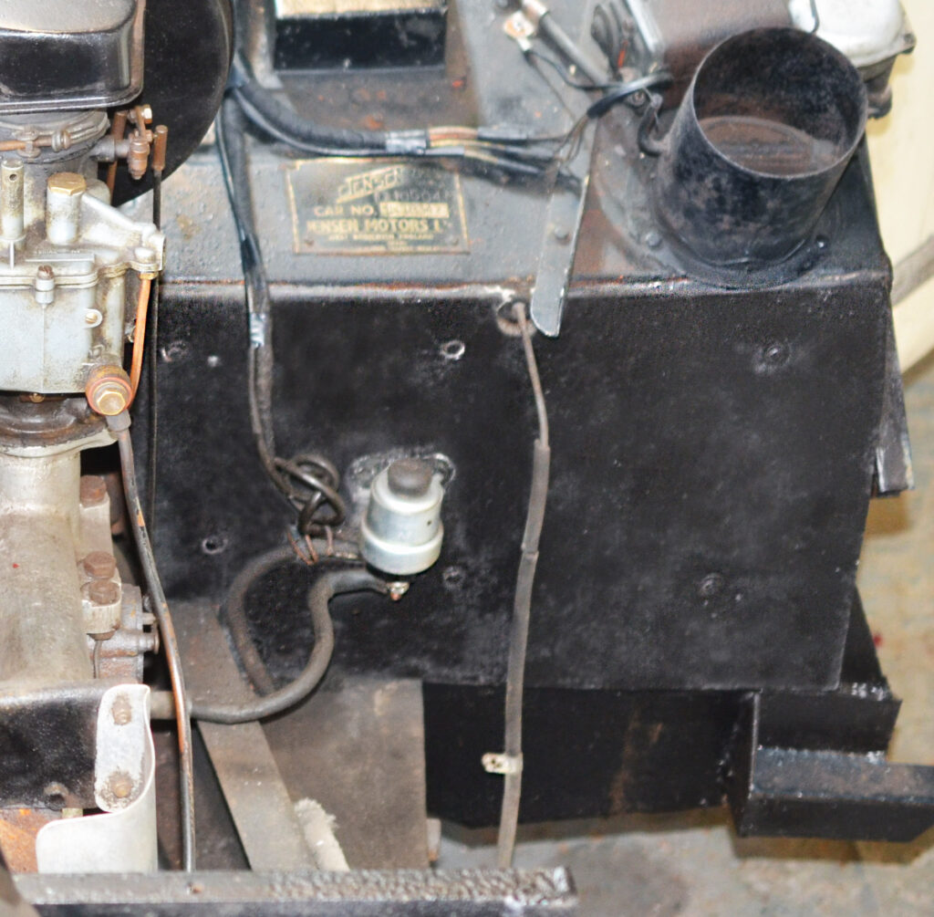
The lower sections of the bulkhead have asbestos like heat shields fitted in place, sold under the tradename, Neolangite. These are screwed directly into the bulkhead. A Lucas starter solenoid is attached to the heat shield, as can be seen half way down on the nearside bulkhead. The wire dangling down is the bonnet opener, which is attached to the inner body panel, once the front is in place. The jack point can also be seen lower right.
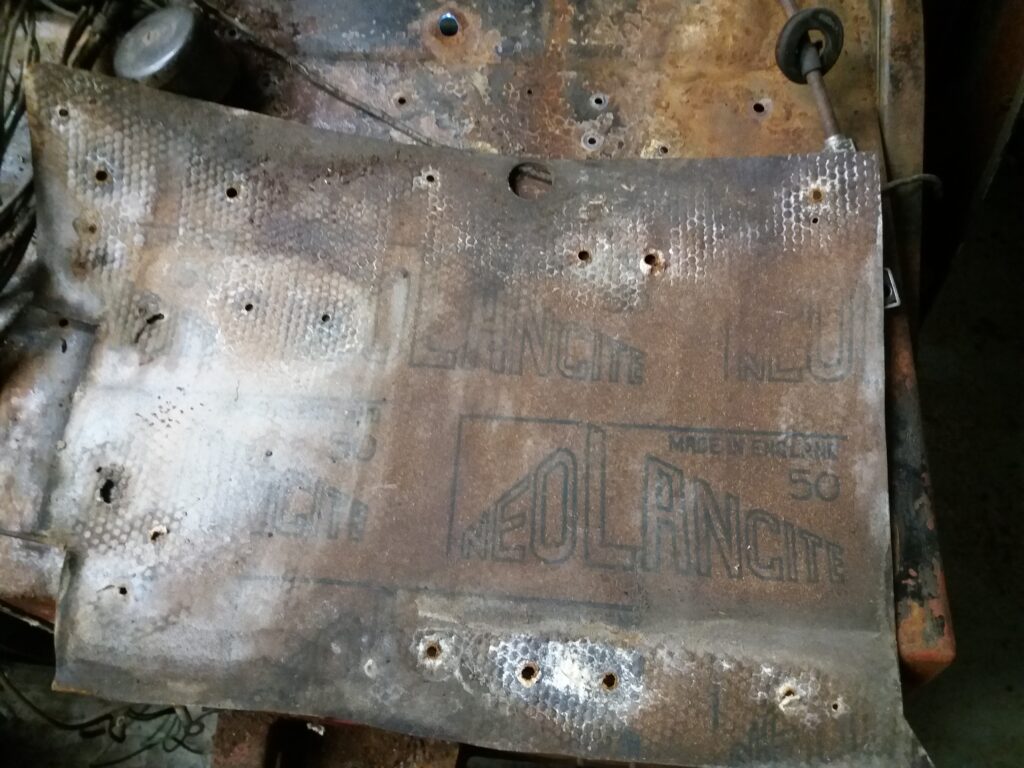
Photograph showing the reverse of one of the Neolangite heat resisting panels mounted to the lower bulkheads (this example from chassis ’88’. Neolangite was first used in 1952, it was a bonded mixture of rubber, gutta-pertha, gum, asbestos and mica.
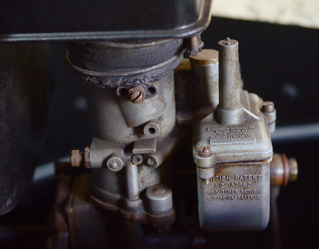
Detail image showing the Stromberg carburetter (car ’63’).
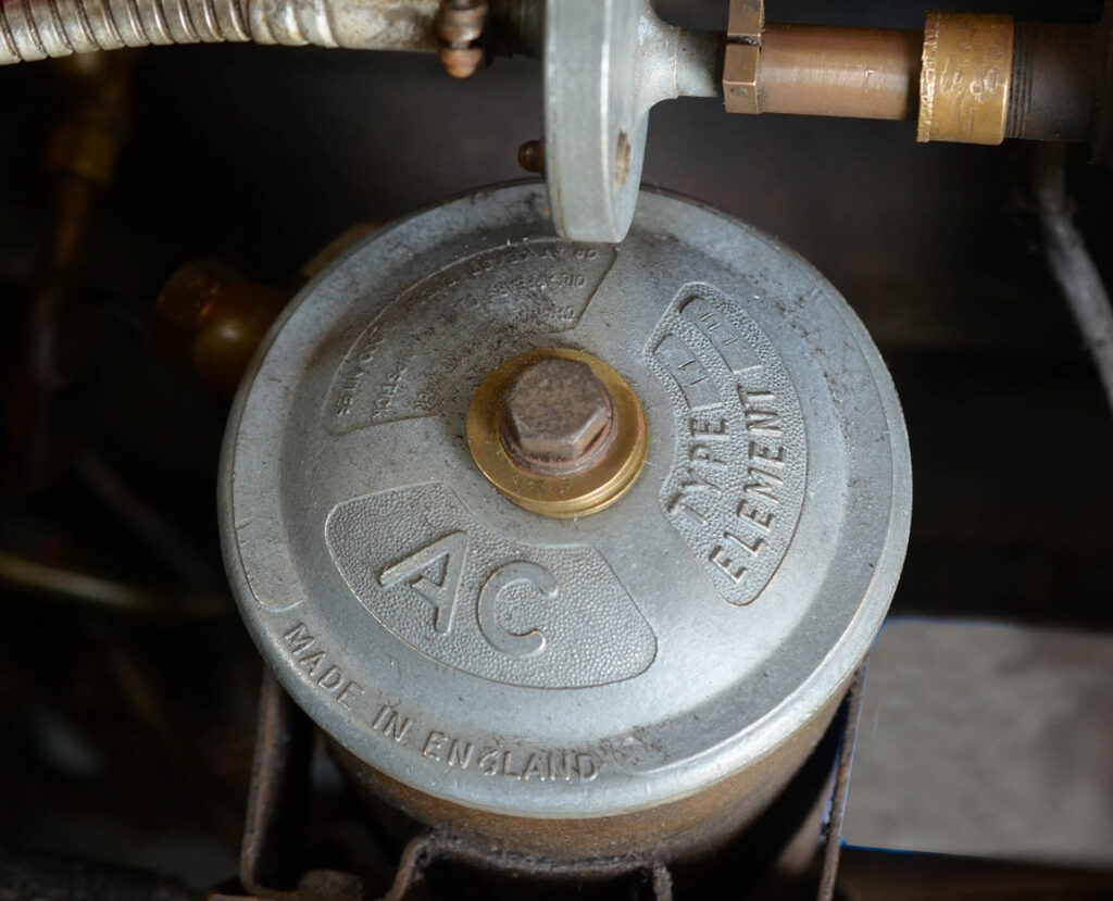
The AC oil filter canister. This is fitted to the chassis just under the dynamo (car ’63’).

Detail showing the Lucas RB310 Voltage Regulator and the main fuse panel typically covered with an original section of millboard, and held in place by two slot head screws (car ’63’).
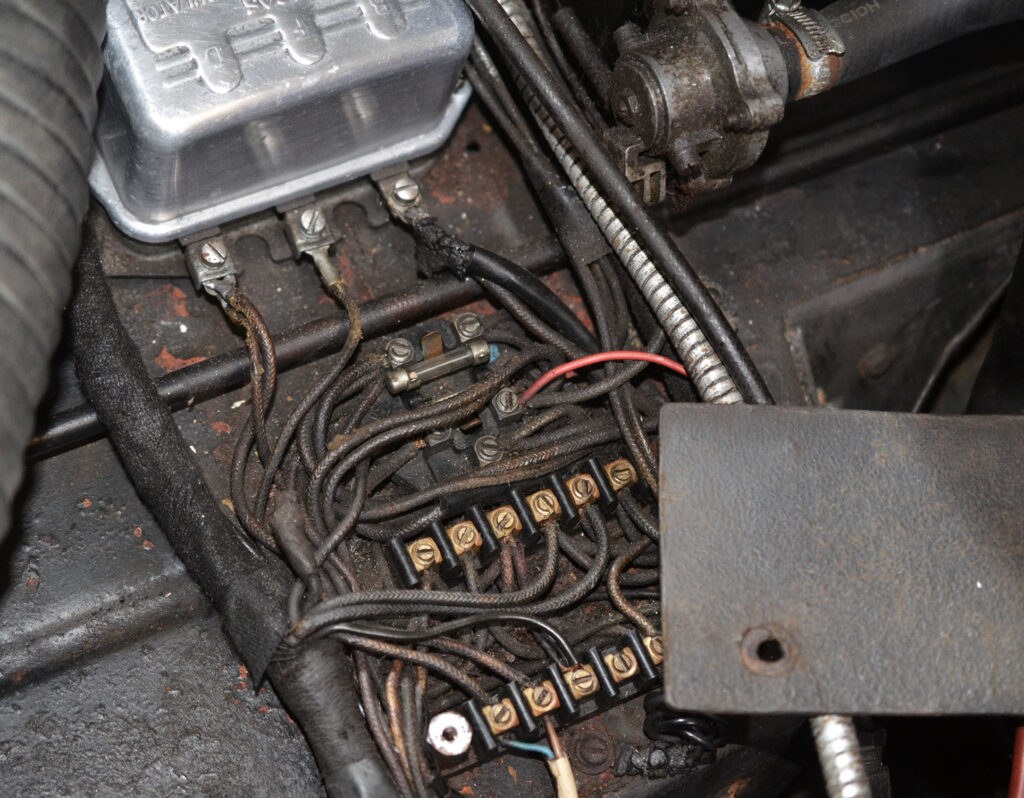
The main fuse board with the millboard cover removed. On ’63’ there is a short millboard cover employed, but a larger one was used on earlier cars. The shorter millboard panel was probably put in place to allow easier access to changing the glass fuses.
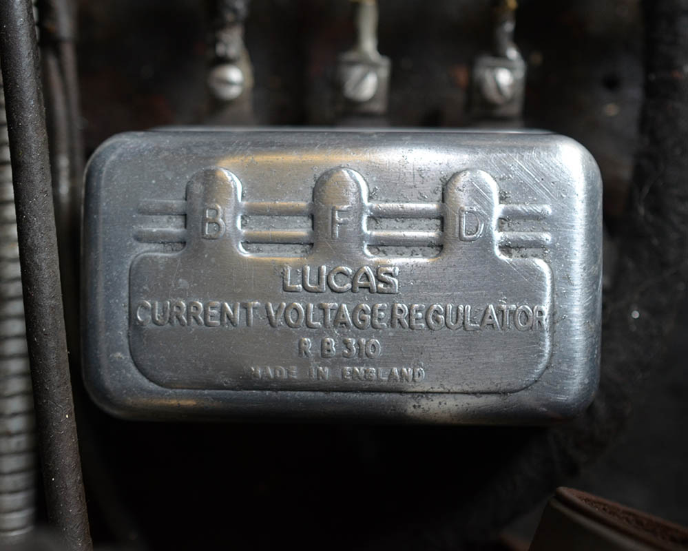
The Lucas RB310 Voltage Regulator, as fitted to ’63’, and many Early Interceptors. Initial cars may have had the Lucas RF95 voltage regulator. In fact Early Interceptor chassis ’41’ has an RF95 regulator, which seems original to the car, as does car ’56’ so it could be that the RB310 superseded the RF95 later in the production run. In regard to cars later than ’63’, both car ’79’ and car ’88’ have the RB310. So far we haven’t had the chance to check any others.
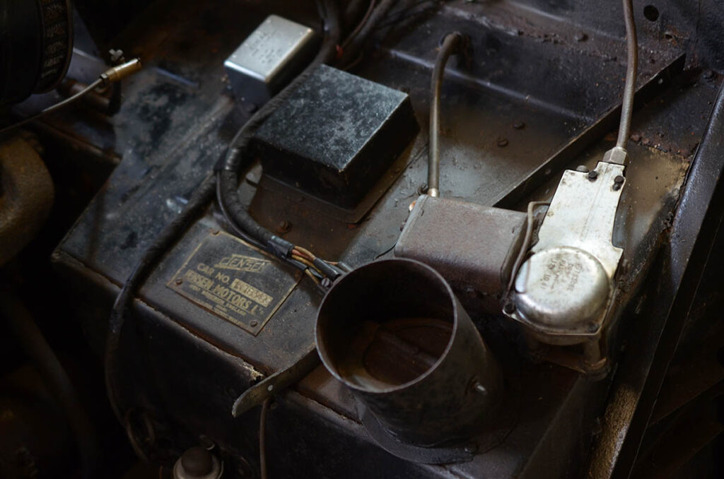
Nearside of the bulkhead on car ’63’. The chassis plate attached with four screws. Above the chassis plate is an optional metal square housing. This was fitted if a radio was fitted, and allowed the back of the speaker to fit in, in turn allowing more room for the passenger’s legs inside. Based on viewing surviving cars, it would seem that many owners decided to include the expensive optional radio set-up. To the viewers left of the speaker housing, is the Lucas DB 10 main indicator relay. To the viewer’s right is the wiper motor. Once the front body section is fitted back into place, the wiper motor is hidden. The circular tube just below the wiper motor is a footwell vent. A 4″ flexible plastic tube attaches to this and runs inside the front body section. Within the tube (just visible), is a rotating flap, which can be closed from the inside of the car. It seems that initial Early Interceptors didn’t have this vent. Likewise we know the last car (chassis ’88’) had two, one each side. The ‘Benjamin Britten’ car, chassis ’84’ also just had one to the nearside, so it remains possible that just the last car, chassis ’88’ had two.
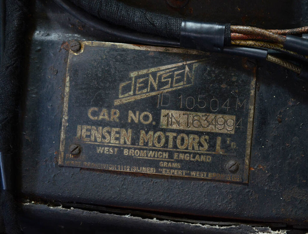
Close-up photograph showing the Interceptor ’63’ chassis plate. The ‘4994’ numbering, directly after the ’63’ is an internal numbering system used by Jensen Motors. The number stamped above the chassis number is the engine number ‘ID 10504M’. Strangely, one will find the chassis plates either stamped like this one – correctly, or stamped with the engine number in the car number box, and the chassis number (car number) stamped above. This anomaly was probably just down to the individual given the job of stamping the plates.
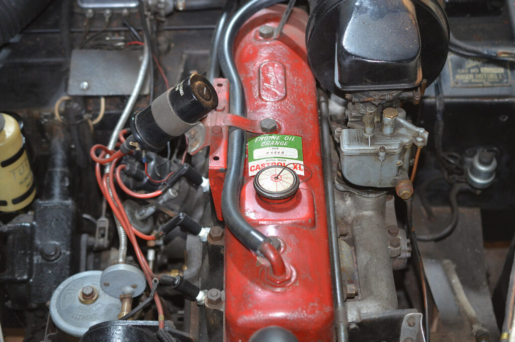
The rocker cover in typical red paint, and with the Austin logo to a raised cartouche. Worthy of note is the special oil filler cap (see image below). The coil with bracket attached to the rocker cover can be seen to the viewers left, whilst to the right can be seen the Stromberg carburetter (car ’63’).
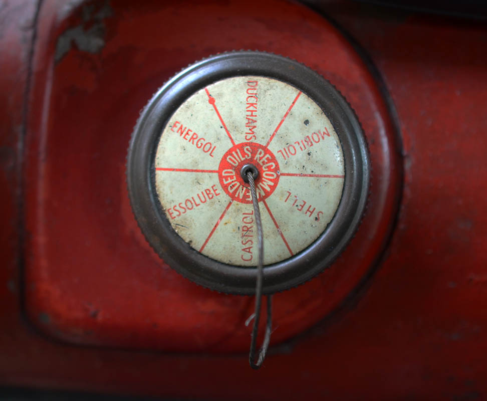
The Austin rocker cover (typically in red paint) had this special oil filler cap showing recommended oils for the engine (car ’63’).
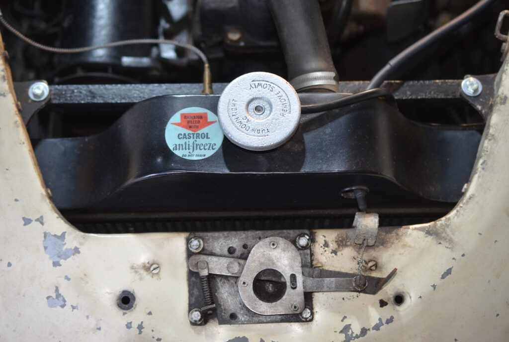
Image showing the radiator , along with the specific AC pressurised radiator cap. To the viewer’s right is the bonnet opening cable, which runs through a circular hole in the radiator, and attaches to the bonnet release catch (car ’63’).
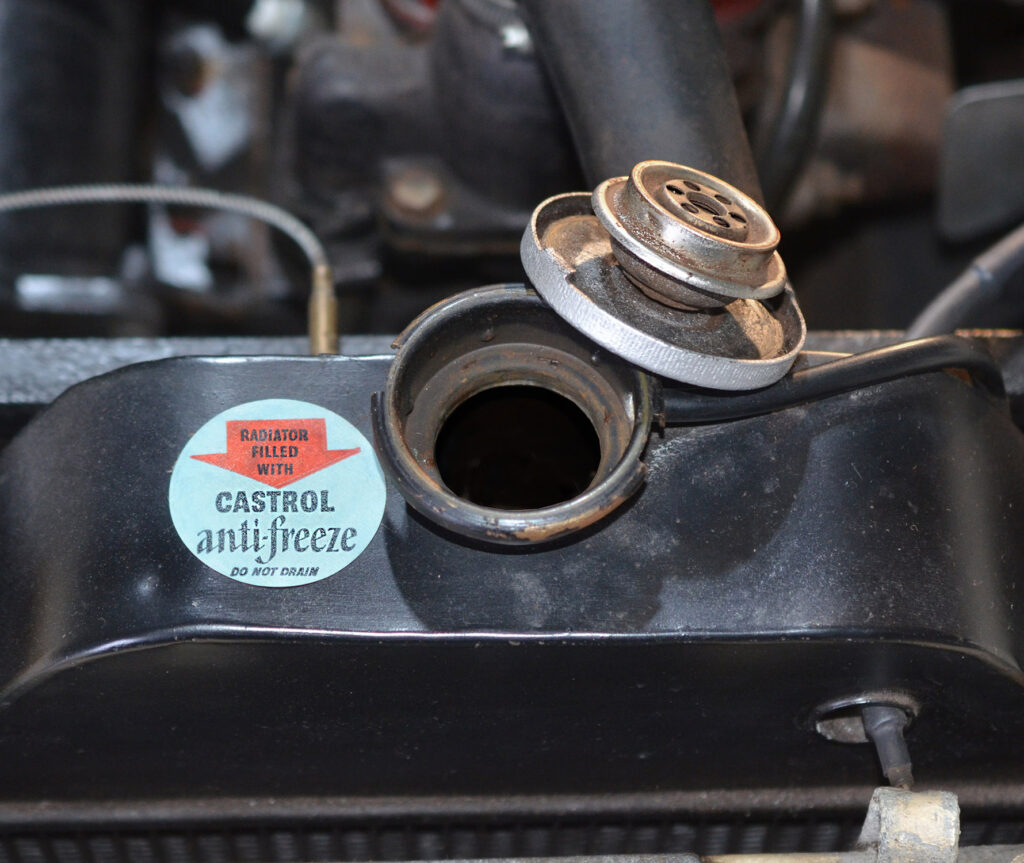
Image showing the inside of the Early Interceptor radiator cap (car ’63’).During the period of the Early Interceptor, Jensen Motors recommended Wakefield Castrol anti-freeze as their first option. Although used by the military during World War II, anti-freeze didn’t see wide-spread use in the immediate post-war years. Many owners were draining the water out of the system if they weren’t using the car during the winter months.
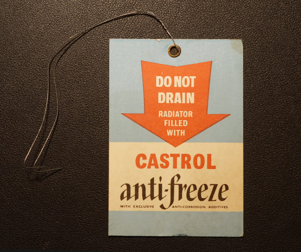
Castrol 1950s / 1960s anti-freeze tie card, which was wire tied around the bottom radiator drain plug. Anti-freeze was an expensive fluid back at the time the Early Interceptor was driving around Britain’s roads. The Early Interceptor handbook stated on page 24, ‘When anti-freeze has been added it is a good plan to tie an anti-freeze label to the radiator drain plug to prevent a garage employee from inadvertently draining the solution’.
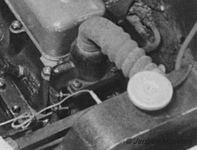
The factory supplied John Bull fabric covered top hose is shown in this period image.

An original factory supplied John Bull top hose (still on car ’63’ when the Museum acquired the car). The John Bull range of top quality radiator hoses generally had a reinforced woven fabric sheath. The applied sheath can be seen in this image.
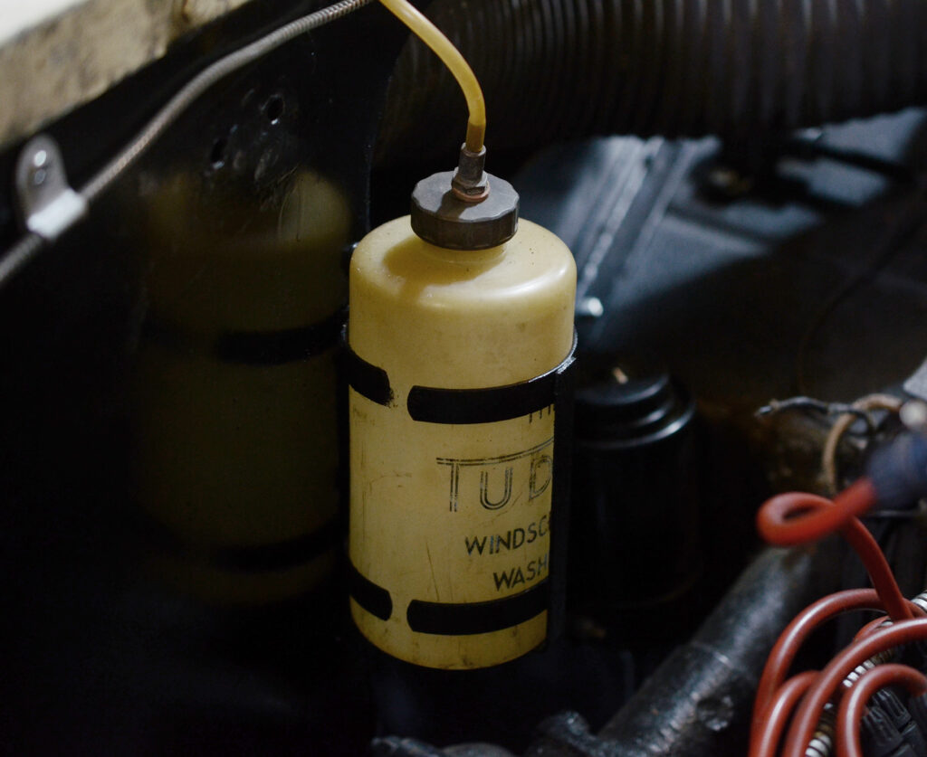
The Tudor windscreen wash reservoir. This was fitted to the off side inner panel by two black painted metal clamps (car ’63’).
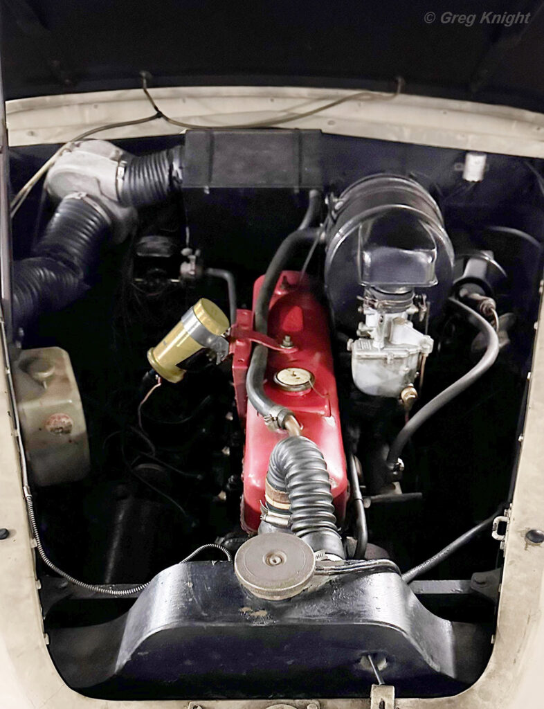
Early Interceptor chassis ’56’ engine-bay. The engine-bay looking very original, bar the later water washer bottle fitted, and the modification of a remote Lockheed brake servo system (which can be seen to the upper left of the image).
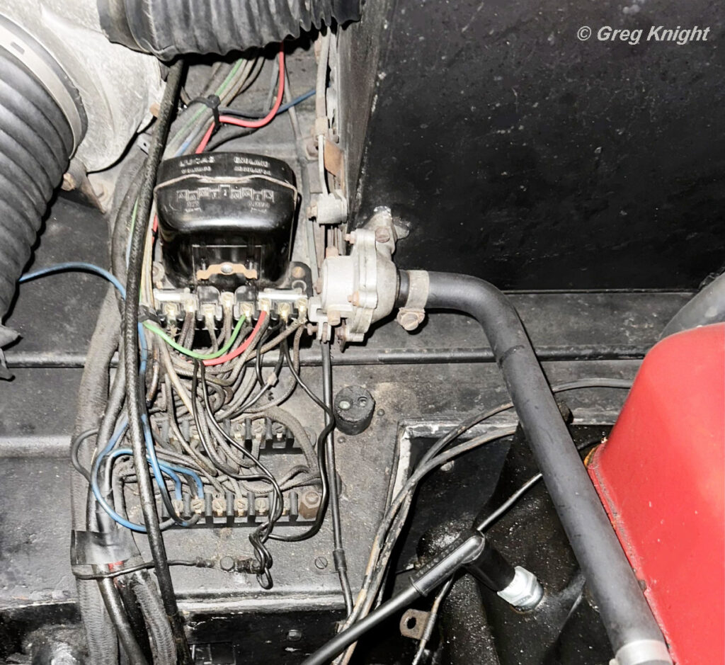
Early Interceptor chassis ’56’ offside bulkhead detail. This car has the Lucas RF 95 Voltage Regulator. The mill board cover to the fuse board is missing from this image. The circular accessory inspection lamp socket can be seen just to the viewer’s right of the fuse board.
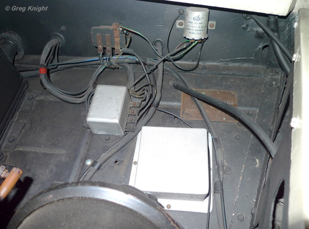
A nearside image of chassis ’56’ engine-bay, which looks pretty much as it would have done when the car left the factory. The white painted box (originally painted black from the factory) is the usual metal box used when a radio system has been installed. The chassis plate is mounted towards the top on this car, although sometimes it is mounted below the speaker box (see chassis ’63’ as an example). The Lucas DB 10 relay box can be seen to the viewer’s upper left of the speaker box. The indicator relay is the small circular canister screwed to the bulkhead. The DB 10 relay allows the sharing of rear lights between indicator, brake and sidelight functions. The other relay in this area is for the horns. A later fitted brake servo can be seen to the bottom of the image.
Early Interceptor Engine-Bay | Engine-Bay Details | Austin DS 7 Engine
Early Interceptor chassis ’88’ was the last Early Interceptor manufactured by Jensen. It shared certain features that were fitted to the Jensen 541, including the Austin DS 7 engine with twin SU carburetters. This was the only early Interceptor to be fitted with the DS 7 engine. That said, Early Interceptor chassis ’83’ was also fitted with twin SU carburetters from the factory, but to the usual DS 5 engine. Chassis ’88’ also had disc brakes all around, and an automatic transmission.
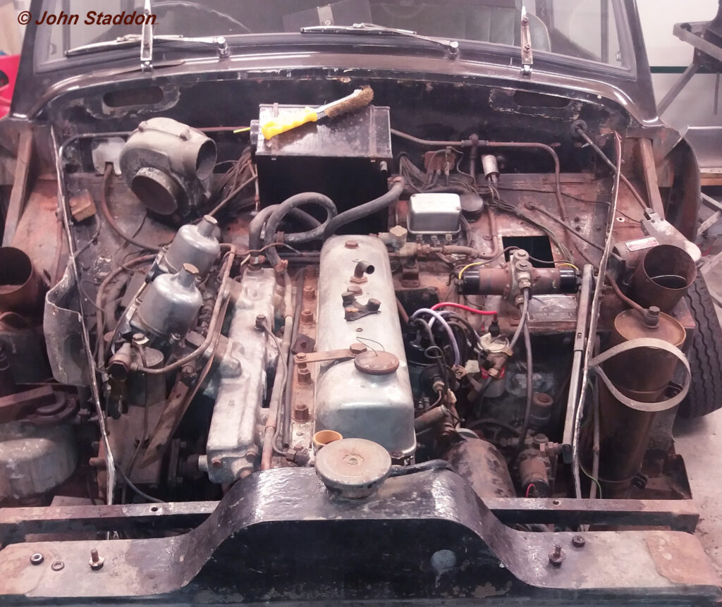
The engine-bay of Early Interceptor chassis ’88’, with the front body section removed. This was the last Early Interceptor produced in chassis number sequence. It is believed this car was used to try out many of the mechanicals that would be fitted to the Jensen 541. The car was fitted with an Austin D7 engine with twin SU carburetters. Additionally the car had hydraulic brakes. Due to the SU carburetters being mounted to the off-side, many components were moved from the off-side to the near-side. This included the Lucas RB310 voltage regulator, the coil, and the dynamo. The main fuse board was retained on the off-side bulkhead, with all the wiring coming off the regulator, and being wrapped behind the heater box and dropping down to the fuse board. The twin interior vents (off-side & near-side bulkhead) can be clearly seen. At which chassis number twin vents were fitted isn’t known, although we know chassis ’63’ had just the one, as did chassis ’84’.
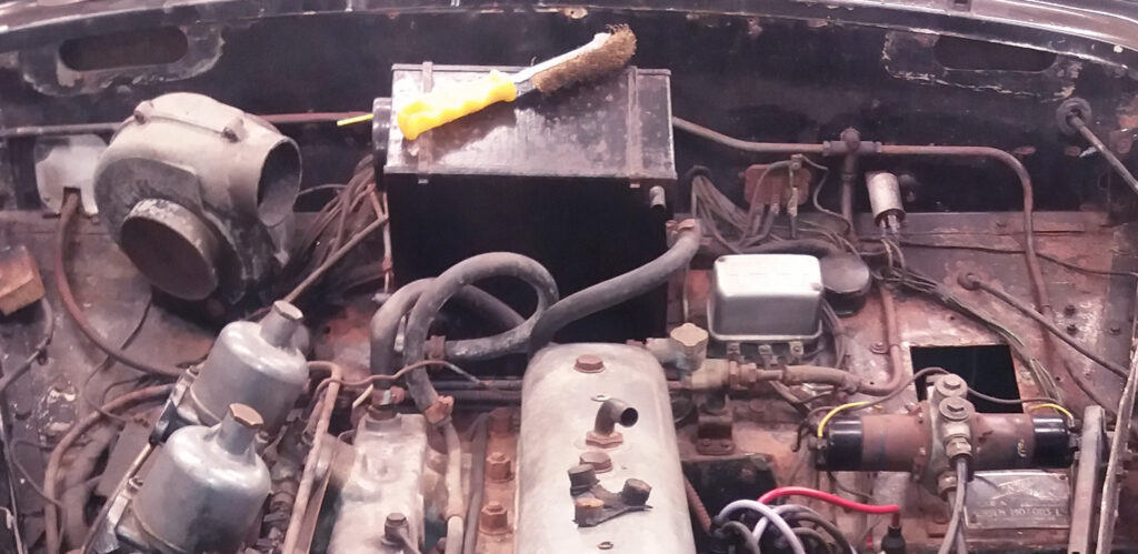
Detail showing the Bulkhead of car ’88’. One can see the wiring coming from the Lucas RB310 voltage regulator, passing around the back of the heater box, and down to the fuse board. The metal speaker box to the viewer’s right of the voltage regulator has been removed as a part of the general strip down for restoration. The fact that ’88’ has the metal speaker box confirms that the car had the optional radio system. Immediately in front of the metal speaker box, is a Lucas petrol pump mounted to a bracket. Most Early Interceptors did not have the Lucas petrol pump.
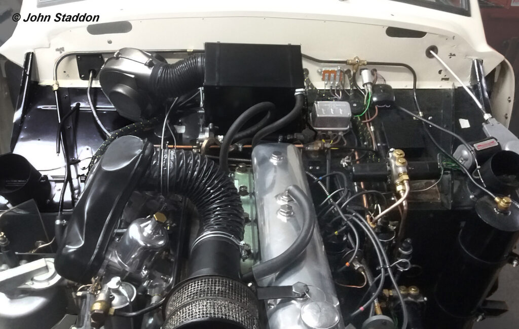
Chassis ’88’ with the engine-bay restored. Some ‘artistic’ licence has taken place, such as the vertical back section of the bulkhead, which would have been finished in black paint from the factory. Likewise, the engine block would have been sprayed black at Jensen Motors.
Early Interceptor Engine-Bay | Engine-Bay Details | Chrysler V8 Engine

1955 published photograph of the chassis ’36’ engine-bay.
Two Early Interceptors were fitted with Chrysler V8 engines. both were left-hand drive cars destined for overseas buyers. The two cars were chassis ’36’ and chassis ’49’.
Chassis ’36’ being fitted with a Briggs Cunningham Chrysler Fire Power 331 ‘Hemi’, and chassis ’49’ being fitted with a Chrysler V8 model 542 engine.
Chassis ’36’ was sold to the Canadian rally driver, Charles ‘Chuck’ Stockey, the ‘Hemi’ engine being fitted at his request. Shortly after taking possession of the car, an article was prepared for Voxair, the in-house magazine of the Royal Canadian Airforce.
The article appeared in the Voxair magazine, volume 4, issue 11 from 1955. In the article is the only known period photograph of the engine-bay. Although of particularly poor printing by todays standards, it is reproduced here.
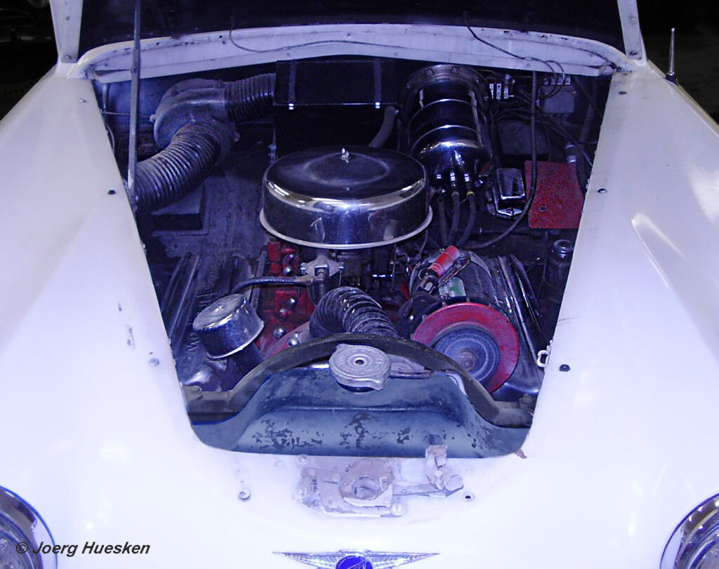
Engine-bay of early Interceptor chassis ’36’. This car one of two left-hand drive cars fitted with Chrysler V8 engine. Chassis ’36’ being fitted with a Chrysler Fire Power 331 ‘Hemi’ engine. Unlike the cars with the Austin DS 5 engines, this car has a large Chrysler Dynamo fitted. The Dynamo also had an extension cable fitted to take it up to the rev counter (the front pulley can be seen just to the viewer’s right of the radiator).
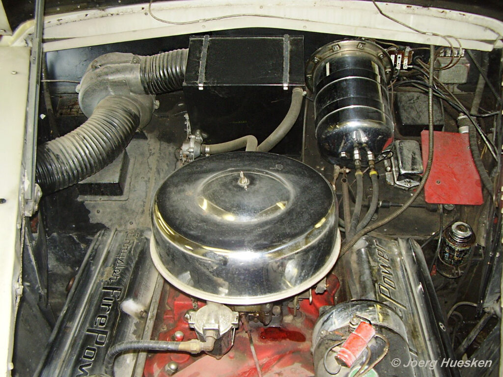
Close-up detail showing the engine-bay of chassis ’36’. The original Chrysler Fire Power engine is still in place. The chrome covers (with raised ‘Chrysler Fire Power’ to each) being correct, as indeed the chrome air filter housing. The large chromed unit to the bulkhead on the viewer’s right is a large oil cooler.
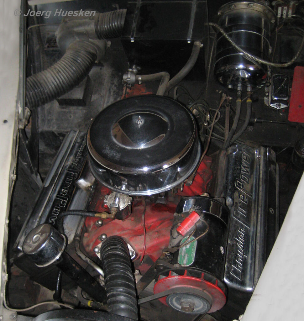
An overview of the engine-bay of Early Interceptor chassis ’36’. The chromed Chrysler Fire Power rocker covers can be clearly seen. This image also shows how tight the engine is within the Early Interceptor engine-bay.
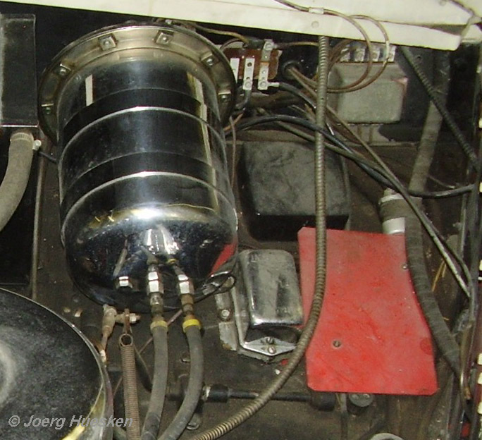
Just to the lower right side of the oil cooler is a chromed Chrysler Regulator. To the right of the Regulator is the cover over the main fuse board (apparently a later owner painted many of the engine-bay parts in red, all of which would have been black). Directly above the fuse board is a black painted metal speaker housing. Interestingly chassis ’36’ had two interior speakers, one of the driver side, and another on the passenger side. Above the speaker housing is the Lucas DB 10 main indicator relay.
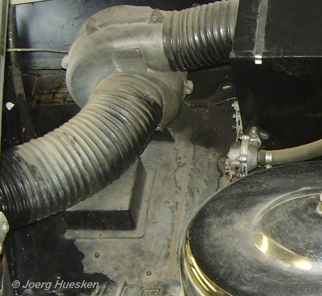
To the viewer’s left of the bulkhead is the heater system, identical to those fitted to all early Interceptors. The chassis plate can be seen upper left of the bulkhead, and the second metal speaker housing directly below the 4″ trunking.
Early Interceptor Engine-Bay
ASSISTANCE REQUIRED: Do you own a largely unmolested Early Interceptor, if so, we would like to hear from you, and hopefully achieve a greater understanding of the changes that went on during the production of the Early Interceptor.
ACKNOWLEDGEMENTS: Jensen Museum |Mick Barnett, Early Interceptor specialist | Derek Chapman | Joerg Huesken, Early Cars Registrar, Jensen Owners’ Club |Rt Hon Sir Greg Knight | Jason Lawrence, Riverbourne Classics | Adrian Longstaff | John Staddon, CV8 Registrar, Jensen Owners’ Club | David Turnage, 541 Registrar, Jensen Owners’ Club.
COPYRIGHTS: Jensen Museum |Derek Chapman | Joerg Huesken, Early Cars Registrar, Jensen Owners’ Club | Rt Hon Greg Knight | Jason Lawrence, Riverbourne Classics | John Staddon, CV8 Registrar, Jensen Owners’ Club
ADDITIONAL INFORMATION: If you have any additional information about this feature, please contact us at archive@jensenmuseum.org or telephone on: +1694-781354
We hope you have enjoyed this feature.
If you would like notification of when new features are added to the Museum website, then why not subscribe.
It’s free, and takes just a couple of minutes. Simply press the Subscribe to our mailing list link below.